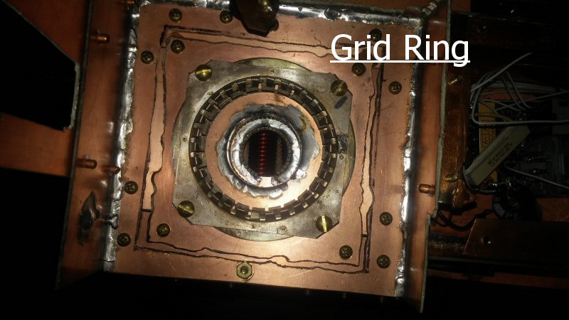
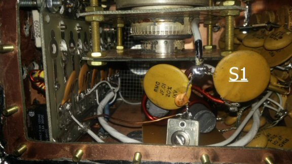
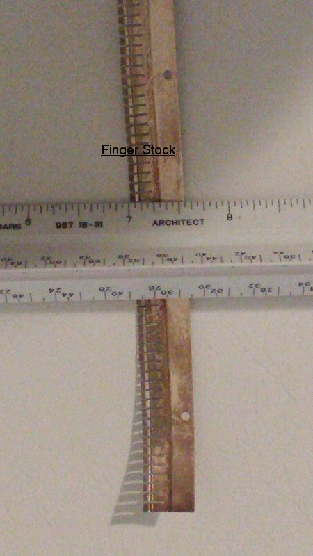
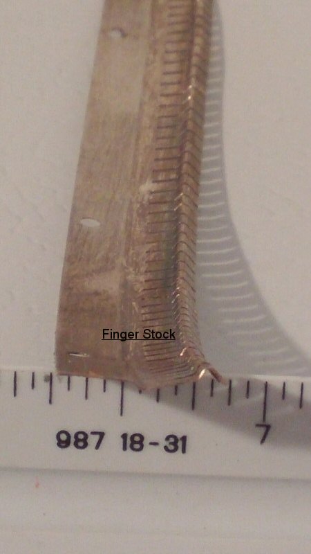
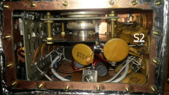
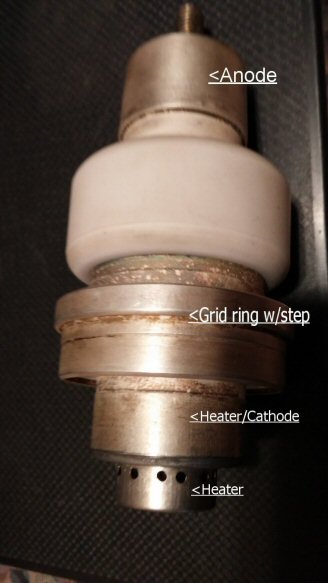
| Hello all, here I will explain how I built this tube socket. The Grid Ring in the photo below, this was just luck. I found this in my junk collection, it was actually for a different tube, but was so close to fitting that I was able to reform the finger stock to make it a tight fit onto the GS35B grid ring, so I used it. I cut three square pieces of double sided circuit board, one to mount the grid ring on and the other two for the two filament connections. I clamped the four pieces together, centering the grid ring, and drilled the four corner holes through all four connectors so they would be lined up vertically, I marked one corner on each one to keep the same orientation, also marked the top side of the three circuit board pieces to keep from inadvertently putting one upside down. At this point I put four screws to bolt the four pieces together. Then I located the exact center of the grid ring hole onto the circuit board piece bolted to it. I then drilled a 1/4" hole through the three pieces of circuit board while all four pieces were still bolted together. This hole is the guide hole for my hole saw, if your hole saw uses a different drill size, not 1/4" then you need to use the appropriate size for your hole saw. Then I disassembled the three pieces. I took a hole saw that was about one inch larger in diameter then the top filament ring and made a score on both side of that circuit board just enough to cut through the copper plating, I did this on both sides. This allows the circuit boards to be mounted directly to the chassis and yet the connections to the tube are isolated/insulated from the mounting screws. I did the same with the bottom piece of circuit board that was to be the connector for the bottom filament connection. I then took the circuit board for the top filament connection and drilled a hole in it with a hole saw that was just about 1/8" larger in diameter then the top filament connection. Then I cut a piece of finger stock that would just go around inside that hole and put it into the hole so it stood up like a wall when the circuit board was lying down, remember this finger stock needs to go down so needs to come out of the bottom side of this piece of circuit board. I had about 1/16" of the finger stock flat side sticking down below the bottom of the circuit board, then tack soldered it in place in about four locations around the circle did same on the other side of the circuit board, then soldered completely around the finger stock on both sides of the circuit board, this made a very strong connector for the filament connection. I then did the same for the bottom filament ring, and it needs to have the finger stock going up instead of down, different size of hole saw of course. Now I was ready to assemble the socket, using appropriate length brass screws and nuts. I used 1/4 20 brass screws and nuts to provide a stable socket. I mounted the grid ring on its piece of circuit board so it could be removed as a unit with all the other socket connections. I connected the grid ring to the top piece of circuit board , which I had cut a hole in that allowed the small lower step of the grid ring to pass through but was small enough to catch the larger step of the grid ring and provide a positive stop for positioning the tube in the socket, with a hole saw, securely with 4 nuts, then I ran 4 more nuts up the screws and put the next circuit board finger stock assembly on the screws, I temporarily put the tube into the socket making sure the grid ring was setting totally down in the grid ring, then using the tube as a guide I placed the circuit board such that the finger stock was connecting about midway on the top filament connection of the tube, then put one more nut on each screw. By adjusting the 8 nuts up and down and finally locking them tight with the circuit board between them, you can make the boards very solid and accurately spaced apart from each other by measuring between the top board and the one you are putting in place. A note here, this assembly is made with the finger stock coming down from the circuit board, the bottom circuit board/finger stock assembly has the finger stock going up from the circuit board, this gives better access to the connections. I used a short piece of #10 wire that I soldered onto the circuit boards, about an inch long solder joint to assure it did not heat up and come loose, close to the finger stock to make my filament/cathode connections. I then placed the bottom circuit board in place using another 8 nuts and adjusting it using the tube for positioning. when finished, the tube went in very smoothly, but with a good connection on each element. This tube has its cathode connection to the top heater connections so make all cathode connections on this side of the heater connection. |